Multimeter Continuity Test: How It Works & Why It Matters
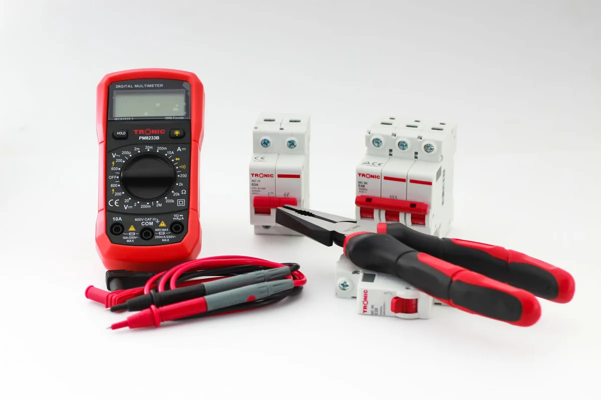
Ever flipped a switch and nothing happened, then wondered if the wire behind the wall is broken? That's exactly the question a multimeter continuity test explained in plain terms can answer for you. Continuity just means an unbroken electrical path.
Your meter checks it in seconds and tells you with a beep.
The idea is simple, but the details matter. Your meter sends a tiny current through whatever you're testing, usually under 1 milliamp. If that current reaches the other probe, you've got continuity.
Per IEC 61010, the safety standard for handheld test gear, the path must be de-energized first. Let's start with what the test really measures.
Quick Answer
A multimeter continuity test checks whether current can flow through a path. Set the dial to the continuity symbol. Touch one probe to each end of the part.
A beep means the path is unbroken. Always run the test with the power off.
What a Continuity Test Actually Tells You
Continuity answers one yes-or-no question. Can electricity travel from point A to point B without interruption?
When the path is clean, resistance sits near zero ohms. Your meter beeps to confirm it. When the path is broken, resistance jumps to infinity and the screen shows "OL," short for over-limit or open loop.
Think of it like blowing through a straw. A clear straw lets air through, that's continuity. A pinched straw stops the air, that's an open circuit.
The beep is a faster way to know without staring at numbers.
That makes continuity perfect for pass-or-fail checks. Is the fuse good? Is the wire broken?
Is the switch actually closing? You get an instant answer, hands-free.
Why This Test Is Hard to Learn From Words Alone
Continuity is a hands-on, visual skill. A photo of probe placement teaches more than three paragraphs of text.
The tricky parts are physical. Where do the probes touch? Which tiny symbol on a crowded dial is the right one?
What does the screen show at the moment the beep fires? These are things you see, not things you read.
That's why we lean on clear photos and labeled shots throughout this guide. If you're new to a meter, watching where the leads go removes most of the confusion. The same logic applies when you're first learning to read a 12V battery, where probe contact makes or breaks the reading.
Finding the Continuity Symbol on Your Dial
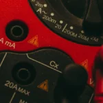
The continuity symbol looks like a sound wave, a set of curved lines fanning out to the right. On many meters it shares a dial spot with the diode symbol, a small triangle pointing at a line.

Here's what to look for on the rotary dial:
- A wi-fi-style arc or "))" shape, that's continuity
- A triangle with a bar, that's diode test
- The letter omega (Ω), that's resistance in ohms
On budget meters, one dial click covers all three. You then press a "mode" or "select" button to reach continuity. On a manual meter, picking the right position matters just as much as it does when choosing the correct battery setting for a 12V check.
Once you land on continuity, most meters show a small beeper icon on the display. That's your confirmation you're in the right mode.
Reading the Screen: 0 Ω, "OL," and the Beep
Three signals tell you everything. The number, the letters, and the sound.
| What you see | What it means | Action |
|---|---|---|
| Near 0.0 Ω plus a beep | Solid continuity, unbroken path | Good connection |
| A few hundred Ω, faint or no beep | Weak or resistive path | Suspect corrosion or damage |
| "OL" or "1" on the left | Open circuit, no path | Broken wire, blown fuse, open switch |
Most meters beep when resistance drops below roughly 30 to 50 ohms. That threshold varies by model. A dead-short wire reads close to 0 ohms.
Watch the middle row. A path can beep faintly at a few hundred ohms and still fail under real load. When the number matters more than the beep, switch to resistance mode and read the actual value.
Setting Up Your Multimeter Step by Step
The setup takes under a minute once you've done it once. Here's the full flow, start to finish.
Plugging the Leads Into COM and VΩ
Get the leads in the right jacks first. This trips up beginners more than anything else.
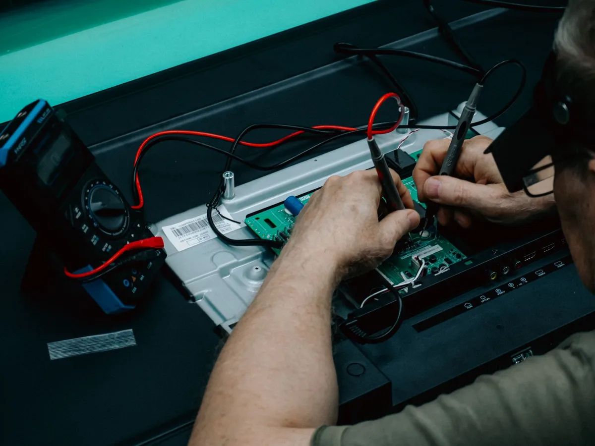
- Black lead goes into the COM (common) jack
- Red lead goes into the VΩ jack, marked with volts and ohms
- Never use the amps (A or mA) jack for continuity
If you swap the leads by mistake, continuity still works, since the test isn't polarity-sensitive. Diode mode does care about polarity, so keep the habit correct. The same lead discipline carries over when you dial in a DC voltage range for other jobs.
The Probe-Touch Self-Test
Before you trust any reading, test the tester. Touch the two metal probe tips together.
You should hear a clean, instant beep and see close to 0 ohms. If the meter stays silent, the battery may be dead, a lead may be broken, or the internal fuse may be blown. Continuity mode needs battery power, so a flat cell means no beep.
This two-second check saves you from chasing a "broken wire" that's really a dead meter.
Placing Probes on the Circuit
Now touch one probe to each end of the path. Press firmly so the tips make real metal-to-metal contact.
- Steady beep, the path is continuous
- No beep and "OL," the path is open
- Flickering beep, you may have a loose connection
Wiggle the wire or connector while probing. If the beep cuts in and out, you've found an intermittent fault, one of the sneakiest problems to diagnose.
Continuity vs. Resistance vs. Diode Mode
These three modes live close together on the dial and confuse a lot of people. Each answers a different question.
| Mode | Best for | Gives you |
|---|---|---|
| Continuity | Fast pass/fail path check | A beep, yes or no |
| Resistance (Ω) | Measuring how good a path is | An exact ohm value |
| Diode | Testing diodes and LEDs | A voltage drop reading |
Use continuity when you just need to know if a wire or fuse is whole. Use resistance when a few ohms actually matter, like checking a sensor or a coil. Use diode mode only for semiconductors.
When to Read Raw Ohms Instead
Switch to resistance mode when a beep isn't enough. A partly corroded joint can beep and still add resistance that starves your circuit under load. Reading the ohm value shows you what the buzzer hides.
What You Can Test: Fuses, Wires, Switches, and Grounds
Continuity shines on everyday troubleshooting. These are the parts people check most.
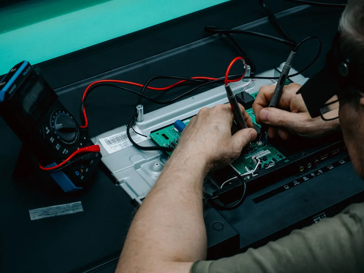
- Fuses: A good fuse beeps. A blown one reads "OL." This is the fastest fuse check there is.
- Wires and cables: Probe both ends to find a break hidden inside the insulation.
- Switches: Beep when flipped on, silent when off. That's a healthy switch.
- Extension cords: Test each conductor end to end to spot a broken strand.
- Ground and bonding paths: Confirm a solid path to ground, key for safety.
In cars, a quick fuse-and-wire sweep is often step one when you're chasing a battery that keeps going flat. A bad ground or a broken feed wire hides behind a lot of odd electrical gremlins.
Common Mistakes That Give You a False Beep
A false beep sends you down the wrong path. Here's what fools the meter and how to dodge it.
- Parallel paths: Current sneaks through another route and fakes continuity. Disconnect the part first.
- Charged capacitors: A stored charge can trigger a beep. Discharge caps before testing.
- Poor probe contact: Oxidized test points give a false "OL." Scratch to bare metal.
- Not zeroing leads: Long leads add a little resistance. Touch the tips together and note the baseline.
- Wrong jack or mode: Leads in the amps jack, or the dial on ohms, throws everything off.
Visual cues matter too. A beep through a green, crusty terminal often means corrosion, not a solid link. Trust your eyes alongside the buzzer.
Safety First: Only Test De-Energized Circuits
This is the one rule you never break. Continuity mode is for dead circuits only. Testing a live circuit can damage the meter and shock you.
Turn off the power. Unplug the device or pull the breaker. Then confirm it's dead with a voltage check before you switch to continuity.
In a workplace, follow proper lockout/tagout practice. The rules from OSHA exist because energized testing causes real injuries every year. Check your meter's CAT safety rating too, since CAT III and CAT IV handle higher-energy environments.
For accurate, traceable measurements, calibration standards from NIST underpin the tools professionals rely on. As of 2026, a reputable fused meter remains the safest choice near mains or automotive systems.
Pro Tips for Catching Intermittent and Corroded Faults
Intermittent faults are the ones that drive people up the wall. The wire works, then it doesn't. Here's how the pros pin them down.
- Do the wiggle test. Flex the harness while probing and listen for the beep to drop.
- Compare to a known-good part. Test an identical working wire or fuse for reference.
- Watch the ohm value, not just the beep. A creeping number reveals a weakening joint.
- Heat or cool the suspect area. Some faults only show up at temperature.
When you can't get a beep at all, a phantom current draw might be the real issue. Learning what a normal background drain looks like helps you tell a dead circuit from a leaky one. And if the trouble points at charging, sorting a battery-versus-alternator fault is the logical next test.
Digital vs. Analog and Dedicated Continuity Testers
Not every tool does continuity the same way. Here's how the common options stack up.
| Tool | Continuity feel | Best for |
|---|---|---|
| Digital multimeter | Beep plus ohm value | Everyday DIY and pro work |
| Analog multimeter | Needle swings, no beep | Reading trends, older shops |
| Dedicated continuity tester | Simple light or tone | Fast, single-purpose checks |
A digital meter is the do-everything choice. It gives you a beep for speed and a number when you need precision. Analog meters lack the buzzer, so you read the needle instead, which is slower for quick checks.
Dedicated testers are cheap and simple, but they can't measure voltage or resistance. If you're going to own one tool, a digital multimeter covers the most ground. And if you're ever caught without one, there are workarounds with no meter on hand, though they're limited.
Frequently Asked Questions
Does a beep always mean the connection is good?
Not always. A beep confirms current can pass, but a corroded joint can beep and still fail under load. When the quality of the connection matters, switch to resistance mode.
Read the actual ohm value instead of trusting the buzzer alone.
Why won't my multimeter beep on continuity mode?
The most common cause is a dead meter battery, since continuity mode needs power to work. Check the leads are in COM and VΩ, not the amps jack. Then touch the probe tips together.
No beep on that self-test points to a battery, lead, or fuse problem.
Can I test continuity on a live circuit?
No. Continuity testing is for de-energized circuits only. Live voltage can damage your meter and shock you, and it gives false readings.
Always turn off the power, unplug the device, and confirm it's dead with a voltage check before switching to continuity mode.
What resistance reading counts as continuity?
A true continuous path reads close to 0 ohms, usually under 1 or 2 ohms. Most meters beep when resistance drops below roughly 30 to 50 ohms, though that threshold varies by model. Anything reading "OL" or infinite means the circuit is open and broken.
What's the difference between continuity and resistance testing?
Continuity gives a fast yes-or-no answer with a beep. Resistance mode gives you an exact ohm value. Use continuity to check if a wire or fuse is whole.
Use resistance when the precise amount of resistance matters, like testing a sensor or coil.
Can I use continuity mode to test a car fuse?
Yes, it's the quickest fuse check available. Remove the fuse from its slot first. Touch one probe to each metal end.
A beep means the fuse is good, while "OL" means it's blown. Pulling the fuse avoids false beeps from parallel circuit paths.

Similar Posts