How to Test Alternator Diodes With a Multimeter
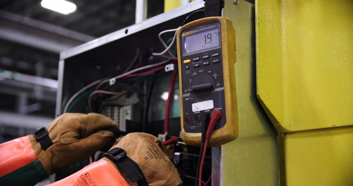
A battery that keeps dying overnight often traces back to one tiny part inside the charging system. Knowing how to test alternator diodes with a multimeter is the quickest way to confirm the fault before you spend money on a new alternator. A single shorted or open diode can leak current and drain a healthy battery while you sleep.
The good news? You can check them with a basic digital multimeter set to diode mode. A healthy silicon diode drops roughly 0.4 to 0.7 volts in one direction and blocks flow in the other.
As of 2026, that reading spec hasn't changed, because it's tied to the physics of the diode, not the brand. Let's start with the warning signs that send most people down this path.
Quick Answer
Set a digital multimeter to diode-test mode. Touch the red probe to each diode and the black probe to the alternator output stud or case. A good diode reads 0.4 to 0.7 volts one way.
Reverse the probes. It should read OL (open). Any diode that conducts both ways or blocks both ways is bad.
Bad Alternator Diode Symptoms That Point to a Rectifier Problem
Bad diodes rarely fail quietly. They leave clues in your electrical system long before the alternator quits for good. Here's what usually shows up first.
- A battery that drains overnight even when everything is switched off
- Dim or flickering headlights, especially at idle
- A high-pitched whine that rises with engine speed
- The battery light flickering on and off
- Undercharging or a battery that never fully tops up
- Radio static or buzzing that tracks with RPM
That overnight drain is the big one. A leaky diode creates a path for current to trickle backward into the alternator while the car sits. If your battery reads fine at night but dead by morning, a diode is a prime suspect.
Before you blame the alternator, it's worth taking a simple voltage reading at the battery to rule out a tired battery first.
The whine and flicker point to AC ripple, which we'll test later. When one diode of the six fails, the alternator's clean DC output gets contaminated with alternating current. Your electronics don't like that one bit.
What Alternator Diodes Actually Do Inside the Charging System
Alternator diodes turn the raw power the alternator makes into usable power your car can store. An alternator produces alternating current (AC), but your battery and electronics run on direct current (DC). Diodes are one-way electrical valves that force current to flow in a single direction.
That conversion is called rectification.
The Rectifier Bridge, Diode Trio, and Stator Explained
The stator is the stationary coil pack that generates three-phase AC as the rotor spins inside it. Those three phases feed into the rectifier bridge, a set of six diodes that flips the negative half of each wave into positive. That's full-wave three-phase rectification, and it's what gives you smooth DC.
Many alternators also carry a diode trio, a small three-diode pack that feeds the voltage regulator and the charge warning light. So depending on the design, you're testing six or eight diodes total.
Why One Failed Diode Can Kill Your Battery Overnight
One bad diode breaks the one-way rule. A shorted diode lets current flow both directions, opening a back door for the battery to discharge through the stator windings when the engine is off. That's your mystery overnight drain.
An open diode is different. It stops one phase from contributing, so the alternator loses roughly a third of its output. The car may still start and run.
It just never charges the battery all the way, and it pushes more ripple into the system.
Why Diode Testing Is a Hands-On, See-It-Yourself Job
Diode testing is a physical job because you have to identify and touch specific components, not just read a number off a dashboard. A wiring diagram or a voltage app can't tell you which of the six diodes shorted. You have to see the positive plate, the negative plate, and the studs, then place your probes exactly right.
This is where a clear photo or a labeled diagram earns its keep. On a bench, a good visual shows the rectifier's two heat sinks, the pressed-in diodes, and the stator leads bolted between them. Once you can spot those parts by sight, the test itself takes just a few minutes.
If you'd rather not pull the alternator apart, you can still get useful answers from an in-circuit ripple test. But for a definitive per-diode verdict, nothing beats getting eyes and probes on the actual rectifier.
Tools You Need and How to Set Your Multimeter to Diode Mode
You don't need fancy gear. A basic digital multimeter with a diode-test setting does the whole job. Here's the short list.
| Tool | Why you need it |
|---|---|
| Digital multimeter (with diode mode) | Reads forward voltage drop across each diode |
| Basic hand tools | To access or remove the alternator |
| Wire brush or contact cleaner | Clean, corroded terminals give false readings |
| Safety glasses | Protects against battery gas and debris |
| Service manual or wiring diagram | Confirms your specific diode layout |
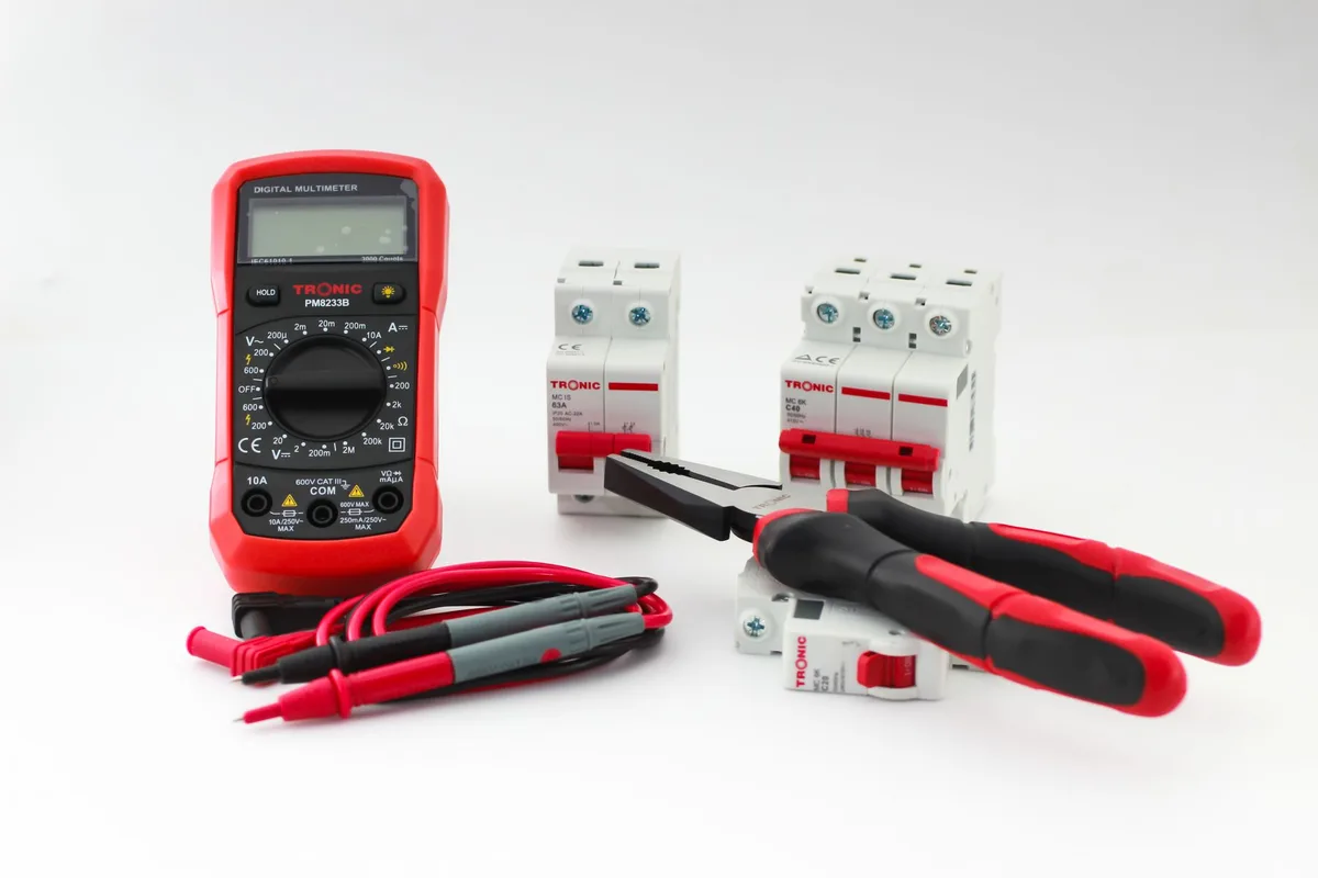
To set up, turn the dial to the symbol that looks like a triangle pointing at a vertical line (▷|). That's diode mode. Plug the black lead into COM and the red lead into the VΩ jack.
Touch the probes together to check it works. The display should read close to zero and the meter may beep.
Manufacturer guidance from meter makers like Fluke's official resources confirms diode mode sends a small test current through the junction to measure its forward voltage. That's exactly what you want here.
Diode Mode vs. Continuity vs. Ohms
These three settings get mixed up constantly, and using the wrong one wastes your time.
- Diode mode: Pushes enough voltage to turn the diode on. It shows the true forward drop (around 0.5V) and reads OL when blocked. This is the correct setting.
- Continuity mode: Only beeps for a near-zero resistance path. It often won't beep across a good diode, so it can fool you into thinking a fine diode is dead.
- Ohms (resistance) mode: Can suggest a diode is good or bad, but readings drift and the numbers are hard to trust.
Stick with diode mode. If your meter lacks one, the same testing habits carry over from other jobs, like when you read amperage across the battery or put the battery under load. The dial changes, the careful probe work doesn't.
How to Locate the Positive Diodes, Negative Diodes, and Diode Trio
Finding the diodes is half the battle, and it's easier once you know the layout. The rectifier bridge sits at the back of the alternator, usually under a plastic cover. It has two metal plates called heat sinks.
One connects to the output stud (the positive side), the other to the alternator case (the negative, or ground, side).

Here's how the parts break down:
- Positive diodes: Pressed into the plate that bolts to the B+ output stud. These handle the positive half of each phase.
- Negative diodes: Pressed into the plate that grounds to the case. These handle the negative half.
- Stator leads: Three connection points bolted between the two plates. Each phase ties one positive and one negative diode together.
- Diode trio: A small separate pack, often near the regulator, feeding the warning light circuit.
Look for three matching junction points where the stator wires meet the plates. Each junction is your test reference. When you probe, you're always checking the flow between a stator connection and either the output stud or the case.
If you can, snap a photo before you disconnect anything. It makes reassembly foolproof, and it gives you a map of exactly where each probe needs to land. That same habit pays off across most electrical diagnostics, including a full battery health check with a meter.
How to Test Alternator Diodes With a Multimeter Step by Step
With the meter in diode mode and the rectifier in view, the test moves fast. Work through the diodes one at a time so you don't lose track. Every diode gets checked twice: once forward, once reversed.
Forward-Bias Test: Probe Placement and Reading
Start with the positive diodes. Touch the red probe to a stator connection point and the black probe to the B+ output stud. A healthy diode reads somewhere between 0.4 and 0.7 volts.
Note the number, then move to the next stator point and repeat for all three.
For the negative diodes, keep the black probe on the alternator case (ground). Touch the red probe to each stator connection. You should see that same 0.4 to 0.7V drop each time.
Reverse-Bias Test: Swapping the Leads
Now flip the probes at each point you just tested. Put the black probe on the stator connection and the red probe on the stud (or case). A good diode blocks flow this direction.
The display should read OL, meaning open.
If it shows a voltage instead of OL, that diode is leaking. This forward-then-reverse pair is the whole test in a nutshell.
Testing the Diode Trio
If your alternator has a diode trio, test it the same way. Probe from each of its three input tabs to the single output tab. You want a normal 0.4 to 0.7V forward reading and OL when reversed.
A dead trio often kills the charge warning light or leaves the alternator not charging at all.
Reading Guide: Good, Shorted, Open, and Leaky Diode Results
Your readings tell you exactly what state each diode is in. Here's the cheat sheet to interpret them at a glance.
| Result | Forward reading | Reverse reading | Verdict |
|---|---|---|---|
| Good | 0.4–0.7V | OL (open) | Healthy diode |
| Shorted | Near 0V | Near 0V | Failed, replace |
| Open | OL | OL | Failed, replace |
| Leaky | 0.4–0.7V | Some voltage | Failed, replace |
A shorted diode conducts both ways, so you get a low number in both directions. That's the classic cause of an overnight battery drain. An open diode blocks both ways, reading OL each time, and it robs the alternator of output.
A leaky diode is the sneaky one. It reads fine forward but lets a little current through in reverse instead of showing OL. Even partial reverse leakage means the diode is done.
One bad reading out of the whole set condemns the rectifier.
The AC Ripple Test at the Battery With the Engine Running
The ripple test catches bad diodes without taking anything apart. It measures the AC leaking into what should be pure DC output. Clean diodes filter out almost all the AC.
A failed one lets it through.
Here's how to run it:
- Start the engine and let it idle
- Set the multimeter to AC volts (the V with a wavy line)
- Touch the red probe to the positive battery terminal
- Touch the black probe to the negative terminal
- Read the display
You want to see less than 0.05 volts AC, which is 50 millivolts. A reading above that points to a diode problem inside the alternator. Turn on the headlights and blower to load the system, then watch the number climb if a diode is weak.
This test pairs well with a standard DC charging check. Healthy charging voltage sits around 13.8 to 14.7 volts DC at the battery. Low DC voltage plus high AC ripple is a strong diode verdict.
In-Circuit vs. Bench Testing: Which One You Actually Need
Which method you pick depends on how sure you need to be. In-circuit testing is faster but less precise. Bench testing takes the alternator apart but gives a clean, per-diode answer.
In-circuit means testing with everything still connected. The catch is that the stator windings and other parts create parallel paths. Those extra paths skew your diode readings, so a good diode can look questionable.
In-circuit is best for a quick yes-or-no using the ripple test.
Bench testing means pulling the alternator and separating the rectifier from the stator. With the diodes isolated, your readings are true and repeatable. This is the way to go when you plan to replace a single diode or want proof before buying parts.
If then logic makes the choice simple. If you just want to know whether the alternator is the problem, run the ripple test in-circuit. If you need to know which diode failed, go to the bench.
Common Mistakes That Give You a False Diode Reading
Most bad diode diagnoses come from testing errors, not bad parts. A few habits keep your results honest. Watch for these traps.
- Using continuity mode instead of diode mode, which misreads good diodes
- Testing in-circuit and trusting numbers skewed by the stator
- Dirty or corroded terminals adding resistance to the reading
- Forgetting to test both directions on every diode
- Confusing a bad voltage regulator with a bad diode
- Leaving the battery connected while probing the output stud
The regulator mix-up trips up a lot of people. A faulty regulator can cause undercharging that looks exactly like a diode issue. If all your diodes test good but charging is still off, shift your focus to the regulator and its wiring.
Clean your connection points before you probe. A thin film of corrosion adds resistance and can push a reading out of range. Thirty seconds with a wire brush saves you from replacing a part that was fine all along.
When a Multimeter Isn't Enough: Dedicated Testers and Load Tests
Sometimes a multimeter confirms the diodes are fine but the charging system still acts up. That's when a dedicated tester or a load test earns its place. Each tool answers a different question.
- Dedicated alternator tester: Loads the alternator and reads output, regulator, and ripple in one shot. Best for a full charging-system verdict.
- Parts-store load test: Free at many auto shops. Best when you want a second opinion without buying tools.
- Oscilloscope: Shows the actual ripple waveform. Best for pinpointing which diode fails under real load.
A multimeter gives you the diode-level detail. These tools give you the big-picture output under stress. Use them together when the fault won't show itself at rest.
Repair a Single Diode, Replace the Rectifier, or Swap the Alternator
Your best fix depends on your skills and the alternator's value. Here's the quick decision path.
If you're comfortable with a soldering iron and the stator tests good, replacing a single diode is the cheapest route. If two or more diodes failed, swap the whole rectifier bridge as one unit. It's cleaner and rarely costs much more.
If the alternator is old, high-mileage, or the stator is also damaged, replace the whole unit. A reman or new alternator saves you from chasing one problem after another. For a daily driver, most people find the full swap the smarter long-term call.
Safety Steps Before You Probe Anything
Disconnect the negative battery terminal before you touch the alternator. This is the single most important step. It kills the risk of a short or an accidental arc at the output stud.
A few more habits keep you safe:
- Never let the B+ stud touch ground or metal tools
- Wear safety glasses near the battery and belts
- Keep sparks away from the battery, which vents hydrogen gas
- Let the engine and exhaust cool before you reach in
- Check that your meter leads and fuse are rated for the job
Batteries hold serious current even with the engine off. Treat the output stud with respect and you'll avoid burns and blown fuses.
Frequently Asked Questions
Can I test alternator diodes without removing the alternator?
Yes. Run the AC ripple test with the engine idling and the meter on AC volts. A reading under 0.05 volts means the diodes are likely fine.
Anything higher points to a bad diode. For a per-diode answer, though, you'll need to bench test.
What does a good alternator diode read on a multimeter?
A healthy diode reads 0.4 to 0.7 volts in diode mode when forward-biased. Reverse the probes and it should show OL, meaning it blocks flow. Readings that conduct both ways or block both ways mean the diode has failed.
Can one bad diode drain my battery overnight?
Absolutely. A shorted diode opens a backward path through the stator windings while the car sits. That slow leak flattens a healthy battery by morning.
It's one of the most common hidden causes of a repeat no-start.
Why do my diodes test good but the battery still won't charge?
The voltage regulator is the likely culprit. It controls how much current the alternator sends to the battery. If every diode reads fine but charging stays low, check the regulator and its wiring next.
Do I use diode mode or continuity mode?
Use diode mode, marked with the triangle-and-line symbol. It pushes enough voltage to turn the diode on and show its true forward drop. Continuity mode often won't beep across a good diode, so it can wrongly flag a healthy part as dead.

Similar Posts